Trendings of industrial
JWinsulatorsAbstract. In this paper, the development of composite insulators at home and abroad
was firstly introduced. Then several common failure forms and mechanisms of
composite insulators were systematically expounded, which mainly included the failure
of sheds and sheaths, brittle and decayed fracture of cores. In addition, the fracture of
composite insulator cores had been the greatest threat to the safe operation of
transmission lines. At last, to provide a reference for the operation and maintenance,
some suggestions and measures for design, production and installation of composite
insulators were put forward from practice.
Keywords: Composite insulator; Shed; Sheath; Core; Failure.
1. Introduction
In 1950s, the America took the lead in manufacturing insulators by composite materials for overhead
transmission lines. With the steady progress of production technology of basic component materials
such as fiber reinforced materials and silicone rubber (SIR) materials, the composite insulator has been
caught more and more attentions, gradually being popularized and used in the worldwide[1]. The
relevant researches and applications of composite insulators in China began in the 1980s, and the
composite insulator was first trial run in 1985. Compared with ceramic insulators and glass insulators,
composite insulators possess superior mechanical properties, good insulation, anti-pollution flashover
performance and are easily installed and maintained [2, 3]. At present, the total number of composite
insulators serviced in power grid of China is more than 7 million, the research, manufacture and
operation have been reached the world leading level [4]. Composite insulator is mainly consisted of
three sections, which are high strength fiber reinforced plastic (FRP) core bearing axial loading, SIR
shed and sheath providing leakage distance and electrical insulation and metal fittings enduring
mechanical loads at both end of the cores[5, 6].
As a outdoor electrical insulation equipment, composite insulators in-service are mainly affected by
environmental factors (such as ultraviolet, ozone, temperature, humidity and contamination, etc.) and
electrical stress factors (such as arc discharge, corona and leakage current, etc.). With the increase of
service life, electrical failures such as interfacial breakdown, shed powdering and fracture of FRP core
will be constantly occurred, leading to the decrease of insulation performance and flashover accidents
[7, 8]. In 1994, CIGRE and IEEE launched an investigation of in-service composite insulator failures,
and the findings revealed that aging, mechanical properties and electrical properties problems are the
main causes, in which 64% of the failures are caused by shed aging. According to the CIGRE statistical
data in 1999, the failure rate of composite insulators is nearly 0.035%, in which the fracture and falling off of fibber accounts for 57%, interface breakdown accounts for 28%, shed deterioration accounts for
14% and the metal fittings damage is only accounting for 1% [8]. In this paper, typical failure cases of
composite insulators in recent years were summarized, which was mainly in order to provide suggestions
and references for the operation and maintenance of the domestic composite insulators in-service.
2. Failures of shed and sheath
Composite insulator shed is usually made of SIR, and it can be divided into equal diameter shed, large,
medium and small shed, large and small shed structures according to different applying environments.
SIR sheds posses good hydrophobicity and mechanical properties, which can supply a good external
insulation and protect the FRP core from erosion by external medias. However, as increasing of service
life, composite insulator shed surfaces will be contaminated, whiten, powered, crazed, harden, deformed
and broken due to the aggressive environmental factors such as ultraviolet radiation, rain, high
temperature, etc., which gradually leads to the decrease of hydrophobicity. When the composite
insulator shed possesses strong hydrophobicity, droplets distributed on its surface will be discrete with
large static contact angles. While the surface of shed will be gradually changed from hydrophobicity to
hydrophilicity when the hydrophobicity of composite insulator shed becomes weak with aging, causing
the formation of water films and discharge channels.
Xinjiang province is located in the northwest of China, where the climate is dry and windy, the
operation condition for composite insulators is very complicated. Besides, the proportion of composite
insulators used in Xinjiang power grid transmission lines is exceeded 90%. In recent years, several 750
kV ultra high voltage (UHV) transmission lines have been built. In some regions, the wind speed is
reached to 42 m/s, and the higher wind speed poses a great threat to the performance of composite
insulators. In 2011, 49 sheds of several composite insulators were damaged to varying degrees found by
transmission line inspectors, and most of the insulators had been running for less than one year, as shown
in Fig. 1. By macroscopic observations and simulations, researchers find that the main reasons for the
failure are the lower hardness and poor deformation resistance of composite insulator shed. When the
wind is strong, the traditionally structured composite insulator shed is easily to swing. In the long run,
the root of composite insulator sheds will be gradually cracked, ultimately leading to fracture
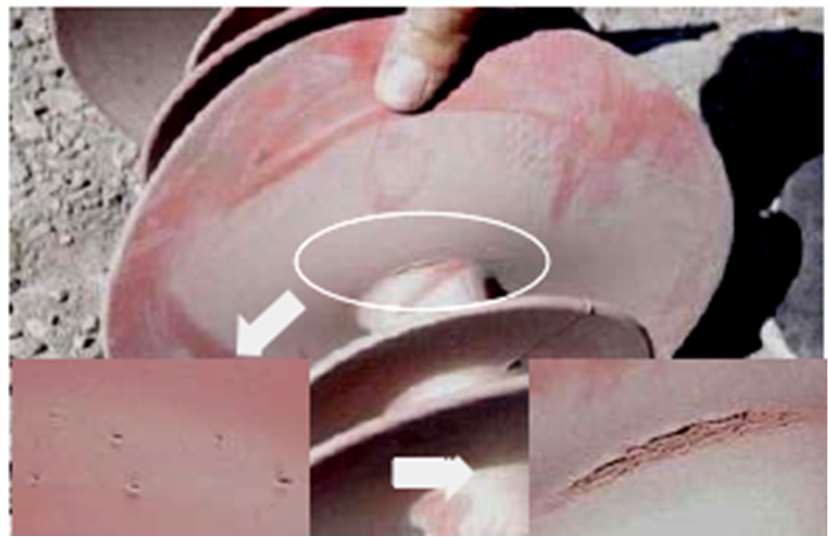
Figure 1. Photograph showing the cracked shed of a composite insulator serviced in Xinjiang transmission line
In April 2013, a composite insulator serviced in a 110 kV transmission line was found to be broken.
It was found that the composite insulator metal fittings of the both ends were blackened. Besides, a lot
of bird droppings and obvious discharge traces were found on the surface of the first shed at the HV end
[10]. It is analyzed that the composite insulator shed surface is unexpected dripped by a certain amount
of bird droppings at the HV end during operation, then the rare bird droppings are gradually flowed
downward along the edge of the shed and formed water belts with the actions of electric field, which
causes the decrease of air gap spacing and partial discharging at the edge of shed. Subsequently, the formation of conductive channel will result in the whole insulator break down quickly, leading to the
trip and power failure of the transmission line.
As the increase of running times, not only the sheds are destroyed, the sheathes will also be suffered
from different degrees of discharges and corrosions, influencing the operation safety of composite
insulators. A composite insulator serviced in a 230 kV transmission line for nine months abroad is shown
in Fig.2, it can be seen that the sheath is severely electrical corroded due to the long-term current
discharges and corrosions
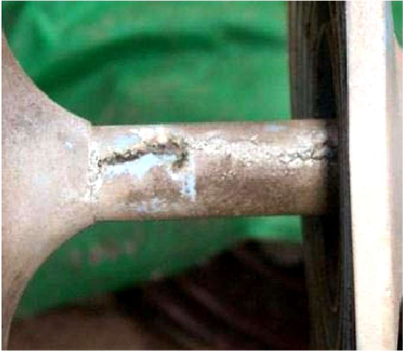
Figure 2. Sheath corrosion of a composite insulator serviced for 9 months in a 230 kV transmission line aboard
3. Fracture of FRP Core
Nowadays, fracture of composite insulator FRP cores has been become the most serious accident in
transmission lines, which greatly affects the safe and stable operation of power system. Besides, this
kind of accidents is outstandingly prominent in HV transmission lines. The fracture of composite
insulator cores is mainly divided into two forms, brittle fracture and decayed fracture. So far, most
accidents of composite insulator fracture are caused by sheath breakdown, which are often happened in
thunderstorms. At run time, defects such as insufficient bonding of cementation surface in local areas,
sheath degumming from FRP core and air gaps existed inside sheath due to improper use of coupling
agent or irregular production processes are often easily to discharge owing to the concentration of
electric fields. Besides the electric resistance of the cementation surface is relatively weak, which will
further promote the defect formation, leading to FRP core breaking, dropping and other accidents.
3.1. Brittle Fracture
Brittle fracture is always a stress induced corrosion process. At run time, the external acidic mediums
will be gradually penetrated into the surface of the FRP core under electric fields as the sealing of
composite insulator sheath is destroyed, resulting in the formation of flat brittle fracture with nearly no
mechanical strength. In addition, cracks will continue to propagate, gradually causing the decrease of
effective bearing areas. When the remaining part cannot bear the mechanical loads, the core will be
brittle fractured[13]. The fracture cross section is always flat, smooth and perpendicular to the axis of
the core, as shown in Fig. 3.
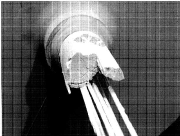
Figure 3. Typical brittle fracture morphology of a composite insulator core
Water diffusion and dissection tests were employed by Zhang et al. to investigate the broken cause
of a composite insulator serviced in the 500 kV transmission line. The results show that the
hydrophobicity of sheds at HV end, middle segment and low voltage (LV) end is all good, and the poor
bonding quality is considered to be the main cause of core fracture. Air gaps will form between the coresheath
interface and induce partial discharges when the bonding procedure is unqualified. This may
cause the aging and erosion of core and sheath, and the brittle fracture of core[14].
In February 2009, a composite insulator serviced for 10 years in phase B of 10# tower of a 220 kV
transmission line was found to be brittle fractured, and the model of the fractured composite insulator is
FXBW-220/100. It can be found that the composite insulator is fractured between the second and third
sheds of HV end, the shed surface is heavily polluted and serious pulverization. It deems that the
composite insulator has been eroded by salt fog for a long time, next the moisture will intrude into the
surface of the FRP core and form an air gap as SIR shed-sheath interface is not tightly sealed or cracked.
Then partial discharge continuously occurs on the core surface and promotes the formation of acidic
mediums. At this moment, the bonding interface of epoxy resins and glass fibers will be continuously
eroded by acidic mediums and moisture, causing gradual decrease in the cross-sectional of glass fibers
and the formation of high stress zones, ultimately lead to brittle fracture of FRP core [14].
A composite insulator operated in phase B of 31# tower of a 500 kV transmission line was found to
be broken in September 2010[15]. Comprehensive analysis results reveal that this composite insulator
fracture is mainly related to the uneven distribution of local electric field strength and the reduction in
mechanical properties of FRP core caused by weak acid corrosion. In addition, the size of grading ring
is unqualified, reducing the effect of voltage equalization, which results in corona discharge on the HV
end sheath surface of composite insulator due to uneven distribution of electric fields and voltages.
Besides, the composite insulator surface is severely polluted, which would also promote the
development of electrical erosions. Finally, long-term discharges gradually lead to the crack of the
sheath and the acid mediums will be slowly penetrated along the cracks until exposing to epoxy resin
fibers, inducing acid corrosions. The mechanical properties of acid etched cores will be sharply
decreased and fractured once the axial tensile strength is lower than the rated loads.
3.2. Decayed Fracture
At present, decayed aging has become one of the primary fracture forms of composite insulator, which
is mainly to do with the product qualities. Decayed fracture is often accompanied by long-term discharge
behaviors inside the core. If defects such as a air gap is formed in the interface between the sheath and
the core due to improper sealing process, it may cause partial discharges in these defects during future
operation processes. However, long time partial discharges will lead to the oxidative decomposition of
epoxy resins, surface erosion of glass fibers and deterioration of SIRs, causing the decayed fracture of
composite insulator after a period of operation. Decayed fracture is usually triggered near the HV end of a composite insulator, and the fracture morphology is always showing obvious carbonization, uneven
cross section and drawing phenomenons.
A fracture analysis of a composite insulator serviced for 5 years in a 500 kV transmission line with
slightly polluted operating environment was carried out by Lutz et al [17]. The macroscopic observation
results indicate that the fracture surface is rough showing no obvious brittle fracture characteristics.
Besides, several punctures can be observed near the fracture by easily removing the SIR sheath from
core, indicating the interfaces had seriously suffered to decayed aging (Fig. 4).
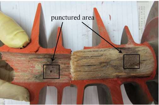
Figure 4. Typical decayed fracture morphology of a composite insulator core
According to Fourier transform infrared (FTIR) spectral curves, the degraded core exhibits a higher
concentration of -OH, -CO and nitrate ion ( -1
NO3 ), and the functional groups of -OH and -CO are mainly
relevant to the hydrolysis of epoxy resins RCOOR H O RCOOH R'OH
2
' + « + ), which is most probably
resulted from partial discharge activities in combination with absorbed moisture and ozone generation:
2 3 3 2
2 2 3 2
3 2 2
2 2
2 2
2 3
HNO O HNO O
2NO H O HNO HNO
NO O NO O
2NO O 2NO
N O 2NO
3O 2O
+ ® +
+ ® +
+ ® +
+ ®
+ ®
®
The analysis results reveal that the fractured insulator exhibited weak sheath-core adhesion due to
unqualified bonding procedure and the effective degradation mechanisms are promoted by the presence
of air gap and water. After long-term operation, the following process may be occurred in the air gaps
of the sheath: air gaps present in rainy or humid period→water vapor permeation→hot spot
formation→sheath splitting→sheath puncturing→FRP core exposure to environment→decayed
fracture of FRP core.
In November 2016, inspectors found that two composite insulators serviced in 30# and 168# towers
of a 500 kV transmission line were abnormal heating and the temperature of local area was 14.2 ℃
[18]. Subsequently, a series of tests such as anatomic observation, X-ray energy spectrum analysis,
scanning electron microscopy (SEM) analysis and FTIR spectroscopy analysis were carried out to
investigate the heating reasons of the composite insulator. The results show that the abnormal heating
phenomenon is mainly related to the decayed aging of FRP core, as shown in Fig. 5. If the composite
insulator is kept running, the FRP core may be soon decayed fractured. This is different from the brittle
fracture of FRP core caused by sheath damage or unqualified bonding quality. Decayed aging is
attributed to a slow corrosion behavior which is always occurred slowly under low performance loads.
Therefore, it is difficult to observe it with the naked eye. The decayed aging of the composite insulator
cores is mainly related to production quality. For this faulted composite insulator, some defects may be
introduced inside the FRP core by employing an improper manufacturing process, then these defects
will cause partial discharges during operation. Furthermore, the persistent discharges lead to the
oxidative decomposition of epoxy resins and erosion of glass fibers, resulting in FRP core decayed aging.
Besides, the size of LV side grading ring of this faulted composite insulator is not meet the standard
requirement, which will further accelerate the decayed aging of the FRP core, thus inducing decayed
fracture.
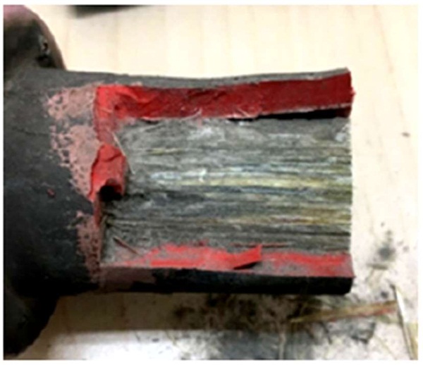
Figure 5 Typical decaying aged morphology of a composite insulator core
It can be concluded that FRP core broken has been accounted for the largest proportion of composite
insulator failures currently. The fracture of FRP core is not only relevant to the quality of itself, but also
directly related to the bonding quality between the core, sheath and two ends metal fittings. However,
in order to ensure the safe and reliable operation of transmission lines, a series of electrical performance
tests such as core penetration, water diffusion, line frequency withstand voltage test and wave impulse
voltage test should be carried out for the same batch of composite insulators to strictly control the
bonding quality. Besides, more attentions should be paid to the connection quality of the metal fittings
and cores during the production process of composite insulators to avoid the formation of internal
defects. In addition, measures such as structural optimization, increasing the thickness of HV side sheath
and number of large sheds should be adapted to increase the climbing distances. Furthermore, the
electric field calculation of the configuration scheme for grading rings should be validated before
constructions, the grading ring size should be also strictly controlled and it is necessary to check out
whether the grading rings are correctly fixed after installation. Moreover, in the process of stress
corrosion tests, researchers found that micro-cracks could be formed at the grinding marks of FRP cores,
which may finally induce the brittle fracture of composite insulators [18]. Therefore, the roughness of
FRP core surface should be strictly controlled.
4. Ending
As a special insulating equipment, composite insulator plays an important role in anti-pollution
flashover of overhead transmission lines. Therefore, in order to ensure the safe and stable operation of
transmission lines, it is of great significance to analyze and discuss the failure forms and mechanisms
of composite insulator. Adopting induction and analysis of common composite insulator faults can
effectively prevent the damages of composite insulator failures, providing guarantee for safe and stable
operation of substations and transmission lines.